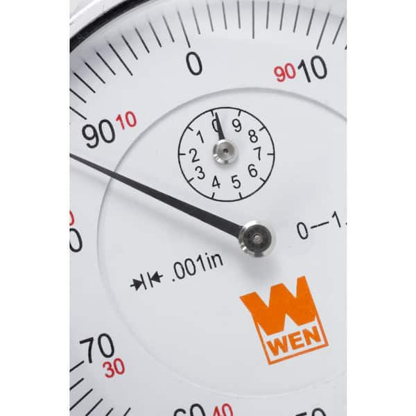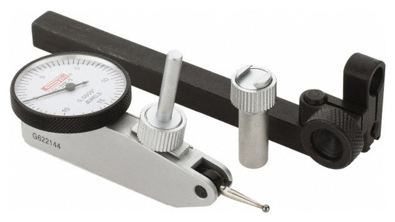
To avoid this, level the rim measurement surfaces of both posts in coordination and rotate precise 90° quadrants using an inclinometer. The same problem would be present in a jig post with a curved measurement surface, if the surface is not concentric with the shaft center.Īnother common source of jig post error is transverse inclined plane effect. Their flat measurement surfaces can introduce an error in the case of a gear or gridmember coupling turned in such away that backlash is present. Jig posts, although useful, can also cause problems if not handled properly. Also, if the jig post has a flat surface, it eliminates curvature error that can sometimes reduce measurement accuracy on small diameters. They accomplish the task of moving the measurement surface to a more convenient location rather than measuring directly on the shaft or coupling surface. These are most often used for rim measurements, but if necessary, can be used for face measurements. Murray Jr., in Centrifugal Pumps (Second Edition), 1992 Jig Postsįor dial indicator measurements, it is sometimes useful to use auxiliary surfaces, sometimes called jig posts. The shift in forces during rotation can cause movement of the magnetic base and erroneous readings. They are not designed for direct attachment to a shaft or coupling that must be rotated to obtain the alignment readings. One example is the improper use of magnetic bases, which are generally designed for stationary service. Note that misuse of equipment can result in costly mistakes.

Do not attach brackets to a movable part of the coupling, such as the shroud. If there is not enough room on the shafts, it is permissible to attach brackets to the coupling hubs or any part of the coupling that is solidly attached to the shaft. This facilitates the use of the indicator reverse method of alignment. The brackets are designed so that dial indicators can easily be mounted for taking rim readings on the moveable machine and the fixed machine at the same time. This also allows more accurate ‘hot alignment’ checks to be made. Brackets eliminate the need to disassemble flexible couplings when checking alignments during predictive maintenance checks or when doing an actual alignment. Dial indicators can easily be attached to brackets and, because brackets are adjustable, they can easily be mounted on shafts or coupling hubs of varying size. Mounting hardware Mounting hardware consists of the brackets, posts, connectors, and other hardware used to attach a dial indicator to a piece of machinery. Face readings, which are used to determine angular misalignment, are obtained as the shafts are rotated and the stem is parallel to the shaft centerline and touching the face of the coupling. Rim readings are obtained as the shafts are rotated and the dial indicator stem contacts the shaft at a 90° angle. It is important to understand that the readings taken with this device are all relative, meaning they are dependent upon the location at which they are taken.

In order to perform the alignment procedure, readings also are required at the 3, 6, and 9 o'clock positions. Measurements taken with this device are based on a point of reference at the ‘zero position,’ which is defined as the alignment fixture at the top of the shaft – referred to as the 12 o'clock position. It yields measurements in (+) or (−) mils.
#Accurate 4 dial indicator series
This movement is transmitted to a pinion, through a series of gears, and on to a hand or pointer that sweeps the dial of the indicator.

When it encounters an irregularity, it moves. The point that contacts the shaft is attached to a spindle and rack.


 0 kommentar(er)
